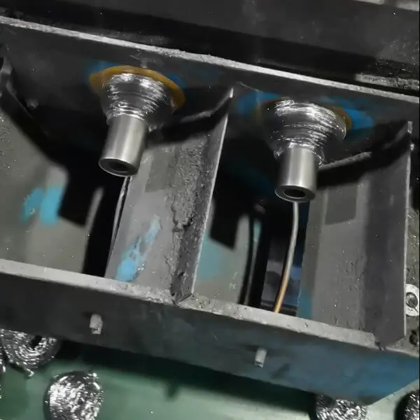
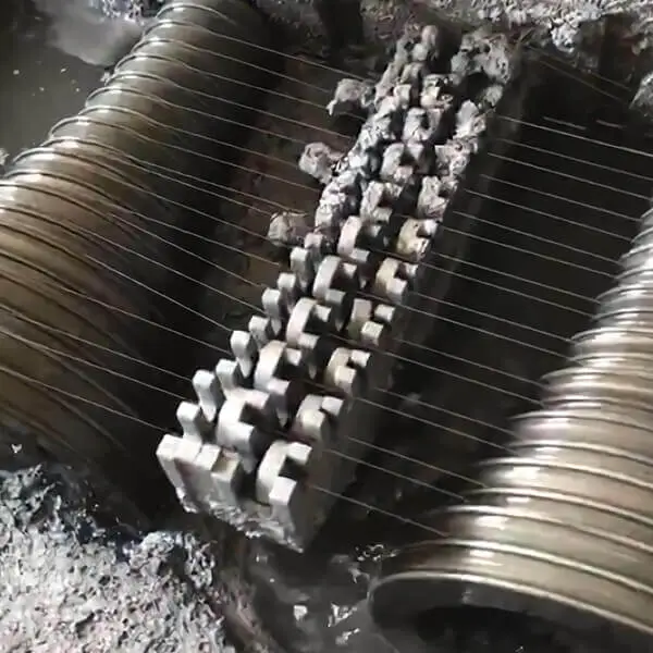
Wire drawing die matching involves four key steps and methods for calculating important data. It can be categorized into single-pass and multi-pass die matching.


Four Key Steps in Wire Drawing Die Matching:
- Select the Blank: Choose the appropriate raw material for drawing.
- Determine Intermediate Annealings: Decide how many intermediate annealings are necessary.
- Calculate Elongation Coefficient: Establish the elongation coefficient for both the drawing pass and the distribution pass.
- Conduct Matching Check: Verify the matching of wire drawing dies.
Common Matching Methods:
1. Traditional Theoretical Matching Method (C Method)
The C Method is based on theoretical calculations and definitions that focus on the drawing process’s initial and exit points.
Symbol definition and related formulas:
- Apertures of various molds: (outlet mold) d1, d2, d3… dn….
- Extension coefficients for each section: (constant speed roller start) μ1, μ2, μ3… μn….
- Gear speed ratios for each tower wheel: (constant speed roller start) ν1, ν2, ν3… νn….
- Sliding coefficients for each section: τ1, τ2, τ3…. τn….
- Cumulative sliding coefficient for the nth tower wheel: Τn = Vn / Un
- Linear speed of the nth tower wheel: Vn
- Speed of copper wire on the nth tower wheel: Un
μn = νn * τn
Below, using a 17-die wire drawing machine as an example, we explain the die matching calculation method:
- Determine the mechanical parameters of wire drawing machine:
Each wire drawing machine manual has equipment parameters, mechanical elongation (or different), that is, the growth rate of the adjacent tower wheel of the wire drawing machine, some manuals have calculations, 17 die wire drawing machine growth ratio: 1.20:1, (last: 1.15:1), i.e. : νn=1.2
- Sliding coefficient τn: For a medium drawing machine, it is generally taken as: 1.02-1.04, so τn = 1.03
- Calculation of the wire’s extension coefficient: μn = νn * τn = 1.2 * 1.03 = 1.236
- Determine input and output wire specifications: Input: 2.80; Output: 1.00
- Die matching calculation: 1.0 – 1.112 – 1.236 – 1.374 – 1.528 – 1.698 – 1.888 – 2.099 – 2.334 – 2.595 – 2.800
This method is typically characterized by:
Application Context: Often used in traditional wire drawing operations where historical data and empirical formulas guide the process.
Advantages: Provides a straightforward approach to die matching with less stringent equipment requirements, making it accessible for various manufacturing settings.
Considerations: While easy to implement, the C Method may not account for dynamic factors such as real-time adjustments in wire properties, which can lead to inefficiencies or defects if not monitored closely.
2. New Theoretical Matching Method (X Method)
The X Method represents a more advanced approach to die matching, emphasizing safety and smooth continuous wire pulling.
The foundation of low-slip cables is the ability to safely (continuously) and smoothly (continuously) pull the cable while minimizing slip. Therefore, the minimum standard for the sliding coefficient is:
- In the die matching calculation, τ3 – τn is required to be 1.0 – 1.01, with an average value of 1.005.
- Safe sliding coefficient τ2.
Here, we introduce the method for determining the safe sliding coefficient τ2. The structure of the 17-die wire drawing machine meets the low-slip drawing performance by reducing the speed ratio of the last tower wheel to achieve a safe sliding coefficient. Therefore, τ2 = (1.2 / 1.15) * 1.005 = 1.049.
- Determine the mechanical parameters of the drawing machine:
Each wire drawing machine’s manual includes equipment parameters and mechanical elongation rates (or differently named), specifically the speed ratios between adjacent tower wheels. The speed ratio for the 17-die wire drawing machine is:
1.20:1 (for the last one: 1.15:1), thus νn = 1.2.
- τ3 – τn is 1.005.
- Safe sliding coefficient τ2 = (1.2 / 1.15) * 1.005 = 1.049.
Calculate the wire’s extension coefficient: μ1 = ν1 * τ2 = 1.15 * 1.049 = 1.206.
- μn = 1.2 * 1.005 = 1.206.
- Determine input and output wire specifications: Input: 2.80; Output: 1.00.
- Adjusting degree calculation: dn = dn-1 * √μn (1.00 – 1.098 – 1.206 – 1.325 – 1.455 – 1.597 – 1.754 – 1.927 – 2.116 – 2.323 – 2.552 – 2.800).
Key features include:
Application Context: Ideal for applications requiring high precision and quality, particularly in high-performance or specialized wire products.
Advantages: Focuses on minimizing sliding and ensuring that the wire undergoes consistent deformation, which enhances mechanical properties and reduces the risk of defects.
Considerations: This method demands high accuracy in both equipment and dies, requiring operators to have advanced skills and a deep understanding of the drawing process. Regular maintenance and monitoring are crucial to ensure the system functions optimally.
3. Absolute Sliding Coefficient Method (J Method)
The J Method focuses on the principle of equal volume during the continuous drawing process. It ensures that the wire rod maintains consistent volume on each tower wheel over a unit time, allowing for efficient material flow.
Basis for Using Absolute Sliding Coefficient for Die Matching:
The wire drawing machine continuously pulls metal wire, and the volume of the metal wire on each tower wheel is equal within a unit of time.
That is,
U1 * S1 = Un * Sn (U1: speed of the wire on the constant speed roller, S1: cross-sectional area of the wire on the constant speed roller).
Then,
Τn = Vn / Un,
Un = Vn / Τn, U1 = V1.
Assuming:
Absolute speed ratio Kn = V1 / Vn.
To
Safe sliding coefficient Τ2 = τ2; the others are Τ3 = Τ2 + 0.001… Τn = Τn-1 + 0.001.
- Determine the mechanical parameters of the drawing machine:
Each wire drawing machine’s manual includes equipment parameters and mechanical elongation rates (or differently named), specifically the speed ratios between adjacent tower wheels. The speed ratio for the 17-die wire drawing machine is:
1.20:1 (for the last one: 1.15:1).
- Safe sliding coefficient Τ2 = τ2 = (1.2 / 1.15) * 1.005 = 1.049.
- For Τ3 – Τn: Τ3 = Τ2 + 0.001… Τn = Τn-1 + 0.001 (to allow for relative slip during punching).
- Determine input and output wire specifications: Input: 2.80; Output: 1.00.
- Die matching calculation:
- First, set the speed of the roller V1 to 1000 and calculate Vn using the speed ratio of adjacent tower wheels.
- Using the absolute speed ratio Kn = V1 / Vn, calculate Kn.
- Calculate the specifications for each die using dn = d1 × √Kn * Τn. (Actually, this is very convenient using Excel.)
(1.00 – 1.098 – 1.204 – 1.319 – 1.446 – 1.585 – 1.737 – 1.903 – 2.086 – 2.286 – 2.506 – 2.746 – 2.800)
Key characteristics include:
Application Context: Best suited for high-speed, continuous wire drawing operations where maintaining a uniform wire diameter is critical.
Advantages: Simplifies calculations related to drawing efficiency, reduces the chances of defects caused by uneven material distribution, and enhances overall productivity.
Considerations: Requires precise calibration of the sliding coefficient, which can be affected by factors such as lubrication, wear on the die, and variations in wire material.
By comparing the three mold matching methods, it’s clear that low-sliding cable has significant advantages in energy saving. Additionally, it reduces the loss of drawing oil and extends the life of the tower wheel, leading to substantial overall benefits. The choice of the appropriate mold matching method should be made based on local conditions, as well as the technical and management levels.
Each of the three methods has its characteristics; it’s not accurate to label one as inferior. Method C has less stringent requirements for equipment and molds, while Methods X and J demand high precision in equipment, strict tolerances for molds, and skilled operators. Combining the X method with a series of molds yields better results.
To achieve effective low-sliding performance and energy savings, using the right molds and lubrication systems is also crucial. Improvements in various aspects are necessary to enhance production and technical levels, allowing the company to advance overall and ultimately achieve energy-saving goals.
For more information about wire drawing dies, please contact us.
E-mail: [email protected]